项目开发笔记 (八) – 依旧是一个重复的轮子
之前说我参与了一个比较 “不一样” 的应用开发,我主要负责其中很多涉及Unity调用原生功能的部分,例如个人用户头像需要调用手机相册摄像头获取,GPS,指南针,内嵌浏览器,包括一些流氓功能(天呀)等等。偶尔还会写几个Unity小模块,其中个人用户头像在显示上,产品要求与各种社交软件一样显示为圆形图片。之前已经实现了如何类似很多社交软件一样获取手机照片 – 传送门。
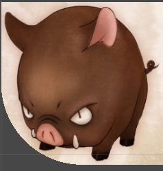
Unity加载显示一张图片,然后使用Shader显示为圆形,这是一个重复的轮子了,但是看了大家的分享之后 发现不是在 Android无法正常裁剪 就是在iOS上显示为白板。所以决定把目前项目中用的分享出来。主要原理就是计算指定范围的像素,然后把像素点的alpha设置为0 (每个像素点都有 RGBA 四个属性值)
如图所示,左下角为UV原点,当纹理uv在 1 区域的时候,也就是满足
uv.x < _Radius && uv.y < _Radius
的时候,当点距离中点的长度大于设定的半径的时候,设置像素透明度为0.其他三个小块以此类推。

如果如果只裁剪部分 1,看起来的效果是这样的:
上Shader代码:
Shader "Self/Circular"
{
    Properties
    {
        _MainTex ("Base (RGB), Alpha (A)", 2D) = "white" {}

        _StencilComp ("Stencil Comparison", Float) = 8
        _Stencil ("Stencil ID", Float) = 0
        _StencilOp ("Stencil Operation", Float) = 0
        _StencilWriteMask ("Stencil Write Mask", Float) = 255
        _StencilReadMask ("Stencil Read Mask", Float) = 255

        _ColorMask ("Color Mask", Float) = 15
        // 以 1 - _Radius 长度为半径的圆形
        _Radius ("Radius", Range(0,0.5)) = 0.5
    }

    SubShader
    {
        LOD 100

        Tags
        {
            "Queue" = "Transparent"
            "IgnoreProjector" = "True"
            "RenderType" = "Transparent"
            "PreviewType"="Plane"
        }

        Stencil
        {
            Ref [_Stencil]
            Comp [_StencilComp]
            Pass [_StencilOp]
            ReadMask [_StencilReadMask]
            WriteMask [_StencilWriteMask]
        }

        Cull Off
        Lighting Off
        ZWrite Off
        ZTest [unity_GUIZTestMode]
        Offset -1, -1
        Fog { Mode Off }
        Blend SrcAlpha OneMinusSrcAlpha
        ColorMask [_ColorMask]


        Pass
        {
            CGPROGRAM
                #pragma target 3.0
                #pragma vertex vert
                #pragma fragment frag
                #include "UnityCG.cginc"

                float _Radius;

                struct appdata_t
                {
                    float4 vertex : POSITION;
                    float2 texcoord : TEXCOORD0;
                    fixed4 color : COLOR;
                };

                struct v2f
                {
                    float4 vertex : SV_POSITION;
                    half2 texcoord : TEXCOORD0;
                    fixed4 color : COLOR;
                };

                sampler2D _MainTex;
                float4 _MainTex_ST;

                v2f vert (appdata_t v)
                {
                    v2f o;
                    o.vertex = mul(UNITY_MATRIX_MVP, v.vertex);
                    o.texcoord = TRANSFORM_TEX(v.texcoord, _MainTex);
                    o.color = v.color;
#ifdef UNITY_HALF_TEXEL_OFFSET
                    o.vertex.xy += (_ScreenParams.zw-1.0)*float2(-1,1);
#endif
                    return o;
                }

                fixed4 frag (v2f i) : COLOR
                {
                    float2 uv = i.texcoord.xy;
                    float4 c = i.color;
                    // 左下四方块
                    if(uv.x < _Radius && uv.y < _Radius)
                    {
                        float2 r;
                        r.x = uv.x - _Radius;
                        r.y = uv.y - _Radius;
                        float rr = length(r);
                        // 裁剪
                        if(rr > _Radius)
                        {
                            c.a = 0;
                        }
                    }
                    // 左上四方块
                    else if(uv.x < _Radius && uv.y > 1- _Radius)
                    {
                        float2 r;
                        r.x = uv.x - _Radius;
                        r.y = uv.y + _Radius - 1;
                        float rr = length(r);
                        // 裁剪
                        if(rr > _Radius)
                        {
                            c.a = 0;
                        }
                    }
                    // 右下四方块
                    else if(uv.x > 1 - _Radius && uv.y < _Radius)
                    {
                        float2 r;
                        r.x = uv.x + _Radius - 1;
                        r.y = uv.y - _Radius;
                        float rr = length(r);
                        // 裁剪
                        if(rr > _Radius)
                        {
                            c.a = 0;
                        }
                    }
                    // 右上四方块
                    else if(uv.x > 1 - _Radius && uv.y > 1- _Radius)
                    {
                        float2 r;
                        r.x = uv.x + _Radius - 1;
                        r.y = uv.y + _Radius - 1;
                        float rr = length(r);
                        // 裁剪
                        if(rr > _Radius)
                        {
                            c.a = 0;
                        }
                    }

                    fixed4 col = tex2D(_MainTex, i.texcoord) * c;
                    clip (col.a - 0.01);
                    return col;
                }

            ENDCG
        }
    }
}
使用说明:
- Unity中创建Shader把上面代码copy
- Unity中创建Material 然后Shader选择上述所创建的
- 最后把Material给要显示为圆形(根据半径的大小 还可以显示为椭圆 圆角图片等)的图片设置为该Material
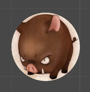
最后完整显示是这样的:
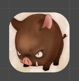
如果调整半径,则显示是这样的:
PS:
经过测试,此Shader在Unity 4.x 全平台(iOS/Android/PC)均显示正常。
-EOF-